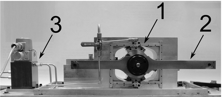
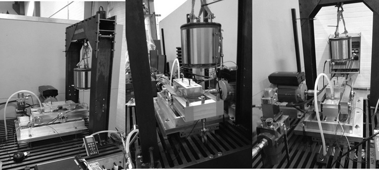
The test rig is shown in Figure A. This experimental setup was originally constructed during the investigations related to a previous research project (Alejandro Cerda's PhD project), and it was extensively modified during the extent of the current one based on the experience gathered during its previous usage. A global view of its current configuration can be seen in Figure B.
Among the modifications, one can mention:
- Replacement of the original hydraulic supply system by one that fits the requirements of the setup in a better way. This included a new high pressure supply pump, as well as the feasibility of working with different lengths for the hydraulic hoses, in order to perform parametric studies.
- Redesign of the tilting arm and its pivoting mechanism, as well as the inclusion of a vibration isolation system, in order to remove unwanted dynamics in the measured frequency range.
- Improvement of the static loading mechanism, in order to achieve higher loading levels, as well as to avoid the inclusion of unwanted dynamics into the measurements.
- Improvement of the dynamic loading mechanism, by including an structure to support the electromagnetic shaker in the desired position.
 |
| Figure A. Conceptual picture of the Actively Lubricated Tilting Pad Bearing Test Rig. The setup consists of a rotating journal supported vertically by a two tilting pads featuring injection nozzles (1) . The journal is mounted on a tilting arm (2), which is pivoted in one end. A hydraulic supply system, composed of a high pressure pump, servovalve and injection lines (3) renders the bearing controllable. |
 |
| Figure B. Actual Installation of the Actively Lubricated TIlting Pad Bearing Test Rig. The setup features a redesigned tilting arm, a vibration isolation system, static and dynamic loading system, a new hydraulic supply system and the necessary instrumentation for performing testing on this prototype system. |